Manufactering Guidelines
PDF version here
This procedure provides clarification and additional requirements for the following:
- Any parts that require dimensional inspection (e.g., machined, stamped, molded, etc.)
- Any parts that require secondary operations (plating, coating, painting, heat-treating, etc.)
- Any parts that require finishing operations (deburring, sandblasting, tumbling, etc.)
- Any printed circuit board that requires repair
Table of Contents
- Engineering Drawing Notes
- Feature Categories
- Standard Title Block (Unless Otherwise Specified)
- Stock (STK) Material
- Drill Points
- Chamfer on Hexagon and Octogon Shapes
- Grind/Lap/Polishing and Stock Allowance
- Part Identification/Etching
- Inspection and Quality Guidelines
- Thread Depth/Thread Length and Pitch Checking
- Thread Quality/Tap Drill Size and Depth
- Material Certifications and Lot Segregation
- Inspection Requirements
- Finishing Operations
- Deburring
- Tumbling
- Media Blasting (includes sand blasting, grit blasting, glass bead, corn cob, etc.)
- Cleanliness Requirements
- Plating/Painting/Coating Operations
- Cosmetic/Appearance Criteria
- Packaging Guidelines
- Printed Circuit Board Repair Guidelines
I. Engineering Drawing Notes
A. Feature Categories
- Weistec drawings will have two categories of dimensions
- Major Feature — Any features having tighter tolerances than those specified on the drawing's standard tolerance block are designated as Major Features
- Standard Care Feature — all other drawing dimensions.
B. Standard Title Block (Unless Otherwise Specified)
- Dimensions are in Inches
-
Decimals
X ±0.030 XX ±0.010 XXX ±0.005 XXXX ±0.0005 - Angles ±.03 degrees
- If a corner is not stated as sharp on the drawing, break all edges for fillets, chamfer, and radii to 0.001" — .005".
-
Polygon Dimesion Tolerances: External:
≤ 0.500 +.000/-
.003 > 0.500
+.000/-.005
Internal: ≤ 0.500 +.003/-
.000 > 0.500
+.005/-.000 - Internal Thread Depth is a Minimum.
- External Thread Length is to the print tolerance.
- Remove All Burrs: See Finishing Operations for more details.
- Sharp for inside or outside corners target is R.000", with R.003" being the maximum allowable.
- When the default (standard) tolerances are specified and the lower specification limit on the dimension is zero or less, the tolerance shall be +100% / -50% of the standard tolerance. An example of this is R.005, where the tolerance will be +.005, -.0025.
- Material — identifies the raw stock used to manufacture the product.
- Anodize and Heat treat — When anodize is noted, anodize to match the dimensions on the drawing after anodizeing operation. Anodize dimensions are standard to drawing tolerance except when a major feature is called out, if the major feature does not specify tolerance the tolerance shal be ±.001 .00When heat treat is noted in material block, part is hardened prior to machining. When heat treat is noted in the heat treat section of the title block, the part is heat treated after machining. Part is expected to meet all dimensions after heat treat process. If heat treat is required after machining, the oxide layer created during the heat treatment process must be present on all surfaces unless otherwise indicated on the drawing.
- Concentricity: Unless otherwise specified, Concentricity tolerance is .002".
- Parallelism: Unless otherwise specified, Parallelism tolerance is .0005"
-
Flatness:
Unless otherwise specified, Flatness tolerance is .0005" maximum. 1 light band = 11.6 µin (0.0000116"). Weistec uses optical flats and laser probes to measure the flatness of lapped and polished surfaces, however when a part requires measurements too difficult to obtain using a standard flatness method such as an optical flat, the print will specify the region requiring interferomic measurements. - Circular Runout: Unless otherwise specified, Circular Runout tolerance is .002".
- Perpendicularity: Unless otherwise specified, Perpendicularity tolerance is .002".
- Symmetry: Unless otherwise specified, dimensional tolerance symmetrical about centerline is .002".
- Centerline: Features shown on centerline must be within ±.0015 of centerline.
C. Stock (STK) Material
- Dimension labeled as STK shall use the manufacturer's finish, dimensions and tolerance, and does not require machining or further processing.
D. Drill Points
- Unless otherwise specified, if a drawing shows a drill point but does not specify an angle, 118° is the standard, but 90° — 180° drill point is allowable. Drawings that specify "drill point acceptable" may use any drill angle. Depth callouts will be measured from the surface to the edge of the shoulder, not the center of the point unless otherwise specified. If a sectional view shows no drill point on a hole, the bottom shall be flat within the dimensions on the detail.
E. Chamfer on Hexagons and Octogon Shapes
Unless otherwise specified:
- External Chamfers on hexagon or octogon shapes are defined as 30° ± 5° starting from a circle inscribed inside the points with a tolerance of minus .001" to .015"
- Internal Chamfers on hexagon or octogon shapes are defined as 30° + 5° starting from a circle inscribed outside the points with a tolerance of plus .001" to .015"
F. Grind/Lap/Polishing and Stock Allowance:
- The manufacturer is responsible for determining what each sub-process should be to achieve final dimensions that meet the drawing specification. The one exception to this is when Weistec Engineering has determined that either product performance or appearance (quality) will be improved by following a certain series of sub-processes. In this case, it will be explicitly called out on the drawing.
- The information below is a guideline.
-
When a
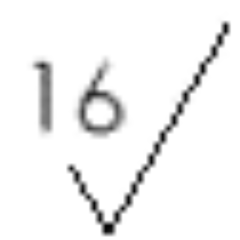 or better (
 ) grind finish is called out, .001" to .002" of stock per side (above nominal) needs to be left over to grind. In some instances, it is possible to achieve a 16 finish directly off a mill or lathe, which is acceptable unless otherwise specified.
-
When a
 or better (
 ) lapped finish is called out, a .001" to .002" of stock per side (above nominal) needs to be left over for lapping. Hand lapping is not acceptable unless otherwise specified on the drawing.
c. When a or better (polished finish)
) lapped finish is called out, a .001" to .002" of stock per side (above nominal) needs to be left over for lapping. Hand lapping is not acceptable unless otherwise specified on the drawing.
c. When a or better (polished finish)
-
When a
 or better (polished finish) is called out, no extra stock is required. Hand polishing is not acceptable unless otherwise specified on the drawing.
G. Part Identification/Etching
- On some Weistec drawings, Engineering will specify that certain information be identified on a specific surface of the part(s) on the drawing. If the drawing says "ETCH", it means that manufacturer will utilize Laser etching where the depth of the etch is 0.001" ±0.001", height of the text to be 0.13" ±0.07", with font type Arial point size 12 or .125". If the surface to be etched is too small to use the standard height, the manufacturer is required to make the text fit in the space available.
- If the drawing says "MARK", it means that the manufacturer could use another method to permanently identify the part at the manufacturer's discretion, using the same height requirement as listed above, but using a depth specification 0.010" ±0.005". MIL- STD-130N should be utilized for guidance (may need further review).
II. Inspection and Quality Guidelines
A. Thread Depth/Thread Length and Pitch Checking:
- Use the appropriate attribute thread gage as called out on the Weistec drawing. To determine thread depth, calculate the number of gage turns required by multiplying the thread pitch by the depth or length of thread, then subtracting one (1) turn for the lead of the gage.
- Thread Length: Measure to last full thread profile, excluding run out.
-
Example: ¼ - 28 threads x .250 deep. See Figure 1.
28 x .250 = 7 turns - ½ turn for chamfer part and ½ turn for lead of gauge = 6 turns of thread.
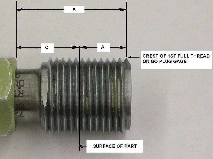
Measure B distance of GO Gage to crest of 1st full thread.
Install GO Gage fully into hole to measure distance C.
Thread Depth A = B - C
Thread Length: Measure to last full thread profile, excluding run out. - When go/no go gauges are used to check thread pitch diameter, up to two (2) turns on the no go gage will be allowed. When there are less than three (3) turns of thread on a part feature, ½ of the available threads will be used to determine the number of turns allowed.
- When the thread does not meet the appropriate ring or plug gage as specified by the Weistec quality staff, and the supplier's gages give a different result, Weistec reserves the right to use a variable thread gaging system, such as that manufactured by the Johnson Gage Company, as the master gage of record to determine if the threads are acceptable. Both the pitch diameter and the functional size of the threads must pass the gage.
- If a "perfect thread" depth is called out on a Weistec drawing, it will indicate the length of usable thread that is required
B. Thread Quality/Tap Drill Size and Depth
- Unless the thread surface is otherwise specified on the drawing, the surface finish of the thread flanks and roots shall be no greater than a 63 finish for external threads and a 100 finish for internal threads.
- Tap Drill Size may not be listed on print; if listed, hole tolerance is prior to threads.
-
Unless otherwise specified on print:
For all holes (including flat bottom holes), maximum tap drill hole depth will be 2.5 x pitch deeper than thread depth. - Tap Drill hole size is based on 70% thread engagement. Reference MS070.
- Internal Threads:
- Major diameter and undercut width: See Machinist Handbook for reference:
-
Major diameter undercut tolerance:
Pitch > 20: -.000/+.010 larger than major diameter
Pitch ≤ 20: -.000/+.015 larger than major diameter - Major diameter undercut width: 1 x Pitch ±.005".
- Lead Chamfer:
- Size: Major Diameter plus .001" to .015"
- Angle: 85° to 125° included angle
- External Threads (see Figure 2):
-
Minor diameter undercut tolerance:
Pitch > 20: +.000/-.010 smaller than minor diameter
Pitch ≤ 20: +.000/-.015 smaller than minor diameter -
Minor diameter undercut width: 1 x Pitch ±.005"
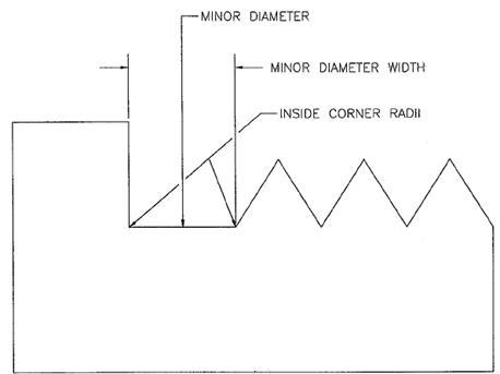
-
Inside corner Radii:
Standard Metric Inside Corner Radii 60 pitch or finer: .5 pitch or finer 0 - .005" 33 - 59 pitch .80 - .55 pitch 0 - .010" 32 pitch or coarser .85 pitch or coarser 0 - .010" - Lead Chamfer
- Size: Minor diameter minus .001" to .015"
- Angle: 85° to 125° included angle
Material Certifications and Lot Segregation:
- All suppliers will provide a Certificate of Conformance for each item supplied when specified on the Purchase Order. Machined products require a Certificate of Analysis indicating chemical composition
- Print will note if Material Lot Segregation is required.
Inspection Requirements
- All products manufactured for Weistec Engineering shall be inspected for dimensional and visual features in accordance with standard ANSI Z 1.4 and/or additional specifications defined on drawings and purchase orders. The required A.Q.L is 0.065 minimum.
- No nonconforming or out of tolerance/specification product shall be delivered to Weistec Engineering unless accompanied by a Waiver with the appropriate approval authority.
- Supplier shall retain product inspection records. Inspection records must be retrievable to facilitate review by Weistec upon request. Records must be held for 10 years.
- All variable characteristics with a tolerance that has 3 decimal places or fewer on machined components must be measured and reported to one extra decimal point. Part pass or fail decisions will be made based on measurements taken to the extra decimal (for example, if a 1.500" +/- .001" OD measures 1.5013" it is rejectable).
- Weistec uses Ra measured in micro inches unless otherwise specified.
-
Part surface finish for all features and details will maintain a surface finish of
 unless otherwise specified.
- When knurling is called out on the drawing, dimensions are prior to knurling unless otherwise specified.
III. Finishing Operations
A. Deburring
- Burr Definition: a non-functional piece of material extending from the parent surface of a part. A burr can be a sharp, ragged projection, firmly adhered, or a loosely hanging projection.
- Due to the sensitive nature of Weistec products, it is important that all components be delivered both deburred and contaminant free without having a process that is excessively aggressive so as to change the print dimensions (most common are broken outside corners). Specifically, any product or process that utilizes silicone cannot be used to deburr product because this material is very difficult to identify and remove after it has been applied. Processes such as AFM (Abrasive Flow Machining), TEM (Thermal Energy Method), ECD (Electro-Chemical Deburring), ECP (Electro-Chemical Polishing), and ECM (Electro-Chemical Machining) are all approved methods due to their perceived ability to deburr without changing drawing dimensions.
- The only other standard approved method for deburring is the use of hand tools such as carbide knives, scalpels, and scrapes, woven fiber tools such as 3M Scotchbrite®, and rotary air tools utilizing Cratex® standard bond, extra fine grit or equivalent silicon carbide soft tools with 180 or finer grit. Any other method is considered not acceptable unless approved in advance by Weistec Engineering.
- Use 10X magnification for inspection of parts. If higher magnification is required, the print will note it.
-
Examples of burrs:
-
Whisker Burr (see Figure 3):
- Loosely attached material generally around thread areas, countersunk holes, and edges of part
- Whisker burrs may be quite small and can peel around edges of feature.
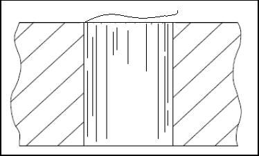
Figure 3 Whisker Burr
-
Silver Burr (see Figure 4):
- Loose sliver of material attached to edge of feature.
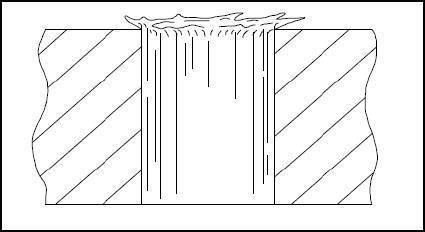
Figure 4 Silver Burr
-
Crowned Burr (see Figure 5):
- Loosely attached material generally around countersunk hole.
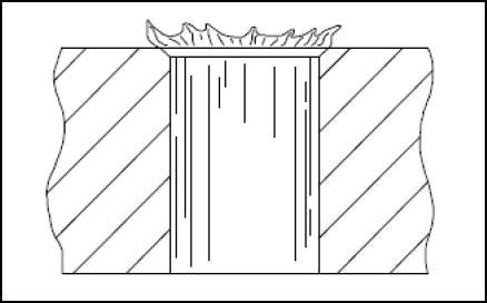
Figure 5 Crowned Burr
-
Hinged Burr: (see Figure 6):
- Loose material generally in hole and milled features.
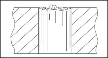
Figure 6 Hinged Burr
-
Rolled Burr (see Figure 7):
- Loose or attached burr on holes, milled and turned features.
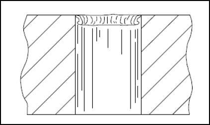
Figure 7 Rolled Burr
-
Feathered Burr (see Figure 8):
- Loose burr generally found on an edge where two dissimilar surface finishes meet.
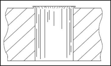
Figure 8 Feather Burr
-
Doughnut Burr (see Figure 9):
- Loose burr that tends to flatten and blend itself into the adjacent material.
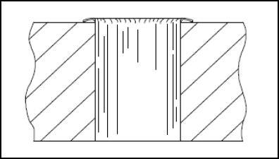
Figure 9 Doughnut Burr
-
Extended Burr (see Figure 10):
- Raised material generally caused by drilling of malleable material.
- This type of burr does not exhibit evidence of material that can break away.
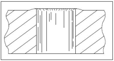
Figure 10 Extended Burr
-
Whisker Burr (see Figure 3):
-
Burrs on Stamped Parts:
- Unless otherwise specified on the drawing, a burr not greater than 10% of material thickness is acceptable provided the burr cannot be detached during normal handling or use.
B. Tumbling
-
Symbol -
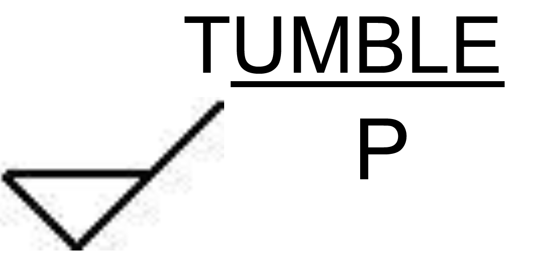
- When this symbol is used in the finish block, it means that tumbling is required. If tumbling is not specified on the drawing, manufacturer may tumble for finishing purposes as long as drawing dimensions are maintained. If drawing has any "sharp" corners denoted, tumbling is not permitted.
C. Media Blasting (includes sand blasting, grit blasting, glass bead, corn cob, etc.)
-
Symbol -
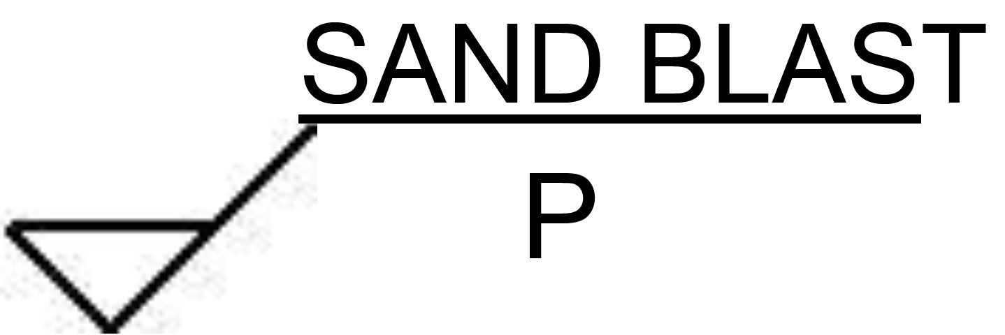
- When this symbol is used in the finish block or called out in the drawing, it means that media blasting is required. If media blasting is not specified on the drawing, manufacturer is not permitted to use it for finishing purposes
IV. Cleanliness Requirements
A. Requirements and Examples
- All parts are to be clean and free of any oil, silicones, cutting fluid, grease pen marks or other contaminants. Parts will be cleaned in an aqueous based cleaning system, alcohol wash, solvent clean or other manner as stated in internal Weistec cleaning procedures or router steps. Any questions on obtaining approval for a cleaning process should be directed to Weistec Engineering (internal suppliers) or Weistec Purchasing (external suppliers) prior to cleaning.
- Parts are visually inspected for cleanliness at 10X magnification to ensure parts are clean and free of any metal chips, dirt, oil, coolant or other contaminants.
- Examples of an unacceptable vs. an acceptable cleanliness part (see Figure 11):
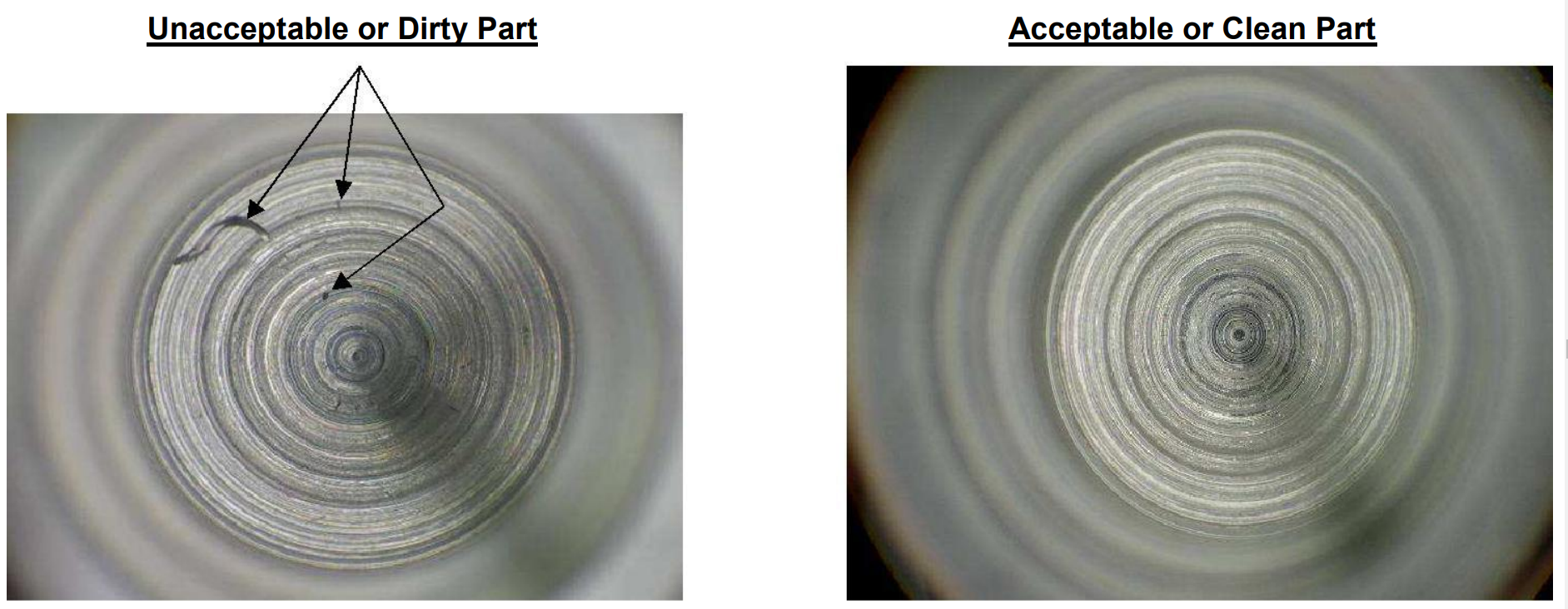
Figure 11 Bottom of Counter Bore Cleanliness Examples
Plating/Painting/Coating Operations
A. Plating/Coating/Painting Requirements
- Unless otherwise specified on the drawing, all dimensions are after to plating/coating/painting.
- Uniform plating coverage is required. If unsure as to uniform coverage, submit a First Article Inspection Piece to QA for review and approval.
- Unless otherwise specified, the following plating thickness tolerances shall apply: +.0002/-.0000”
B. Plating/Coating Threads
- For some small threads, the thickness of the plating/coating can cause a defective thread. In these cases, Weistec engineering has specified a special pitch diameter on the drawing which will need to be undersized/oversized as machined. In these instances, Weistec also utilizes the same drawing to specify the plating/coating process thickness and/or the thread tolerance after the plating/coating process.
- Unless otherwise specified threads shall not be painted but must be masked prior to painting.
C. Product Color
- The Weistec standard for drawing call outs on color specifications is either the Federal Standard Color Chart - 595 or the Pantone Matching System. In some instances, Weistec will identify the paint manufacturer's name and that manufacturer's color name/number. In the case of anodized and hard coat (Sanford process) products, Weistec requires compliance to MIL-A-8625, and the following color ranges:
- Blue: to be no darker than FS 35109 and no lighter than FS 35450.
- Black: to be no darker than FS 17038 and no lighter than FS 36081.
- Gold: to be no darker than FS 20266 and no lighter than FS 23594.
- Green: to be no darker than FS 14062 and no lighter than FS 34259.
- Red: to be no darker than FS 11136 and no lighter than FS 31400.
VI. Cosmetic/Appearance Criteria
A. Requirements and Examples
- Unless otherwise specified, all machined part surfaces are to be free of any cosmetic defects such as nicks, scratches, dents, protuberances, weld indentations, weld splatter, or gouges. However, typical machine tooling marks on the surface are acceptable provided that they meet the surface finish specification. These characteristics will be considered defects if they are larger than .003" deep or .003" wide or long.
-
Examples of Unacceptable Conditions (see Figure 12, Figure 13 and Figure 14):
Scratches on part greater than .003” long
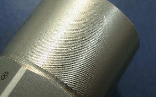
Figure 12 Unacceptable Scratches on Part Example
Machining scars and weld splatter greater than .003” wide and tall
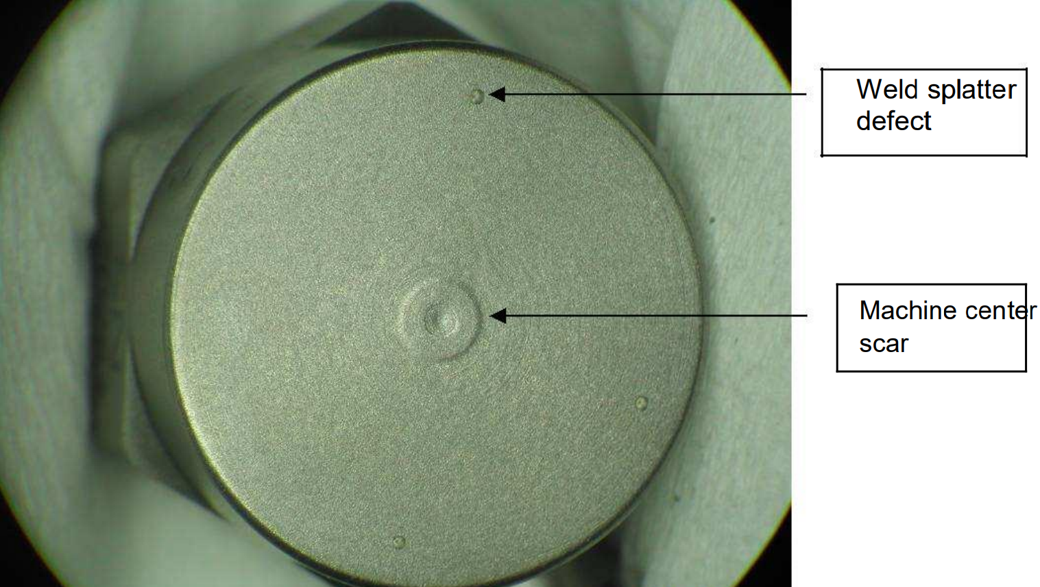
Figure 13 Unacceptable Machining Scar and Weld Spatter Example
Notes:
- Lapped parts may have micro scratches on flat surface from lapping media.
- Part must pass surface roughness and flatness requirements.
- Print will specify ―No Scratches‖ if lapped surface must be pristine.
Nicked/damaged thread greater than .003” deep
(disregard the etched letter X and arrow on part)
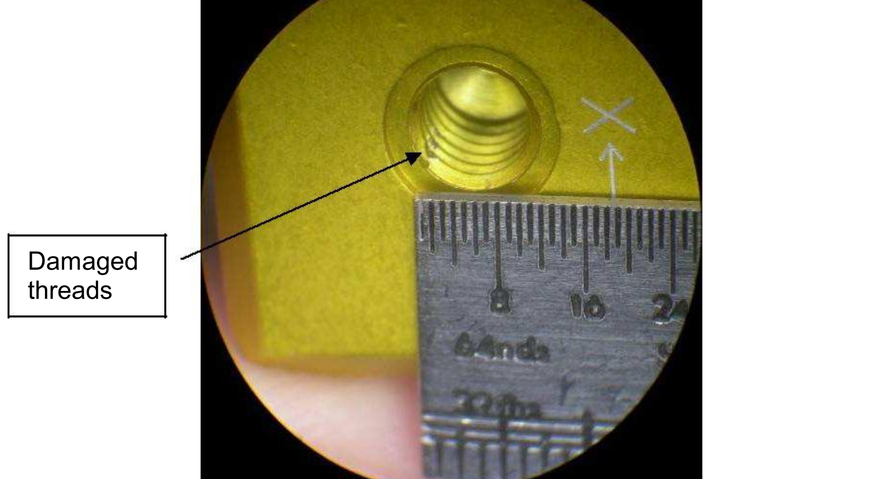
Figure 14 Unacceptable Thread Damage Example
(disregard the etched letter X and arrow on part)
Figure 14 Unacceptable Thread Damage Example
VII. Packaging Guidelines
Requirements
- It is the supplier's responsibility to package supplier's parts to limit the potential for handling damage defects. It may be necessary to package and transport delicate parts in individual compartmentalized plastic packaging.
- Compartmentalized packaging will be periodically cleaned by the supplier to ensure that there is no foreign matter in or on them.
- Suppliers delivering electro-statically sensitive material shall utilize appropriate ESD-safe packaging.
- Un-lined corrugated containers are not acceptable.
- Recommended packaging for suppliers is listed in procedure EN1107.
VIII. Printed Circuit Board Repair Guidelines
A. Warranty Repairs - no charge to Weistec
- Units returned to Suppliers against RMA's in response to MRR or CAR's from Weistec Engineering should be credited upon receipt. If the units are repaired, they should then be re-invoiced at the PO cost as credited. This is standard Weistec Engineering. procedure.
B. Non Warranty Repairs - this would include units not considered a warranty repair by the Supplier. Refer to the following guidelines:
- If the supplier decides that a unit is not covered by their warranty, Weistec should be contacted immediately. Non-warranty repair work should not be done unless Weistec approval is granted.
- A repair cost should not exceed 25% of the purchase cost of the unit. Suppliers should not repair units unless it is certain that the cost will not exceed this allowance.
- Upon approval from Weistec to repair a board, a purchase order will be issued to cover the repair cost. In this case, the supplier should re-invoice the original PO cost that was credited and also prepare a separate invoice for the repair cost as approved.
- There may be circumstances that dictate actions outside these guidelines. A stock out at Weistec, a large lot quantity or a special run board could be exceptions. Weistec will provide specific actions in these cases. If in doubt, contact Weistec.
C. Repair Expectations - repaired units will be considered like new.
- Functional testing, if required, for repaired assemblies must be performed prior to returning the assembly to Weistec. Contact Weistec for fixture and procedure if necessary.
- A Certificate of Compliance must be provided with the repaired units' and needs to include the revision level that the assembly was repaired to
- Programming for components may be the original revision when the assembly was built.
- All cleaning and manufacturing guidelines (lead trimming or component placement) listed in the assembly documentation must be met.
- Notify Weistec Engineering if units are scrapped so PO(s) can be adjusted.
D. Sheet Metal
- The tolerances in this specification shall not override those provided on engineering documents, blueprints, and specifications. In all cases blueprint tolerance or work order instructions shall override this standard.
- Dimensions whose tolerance must be held closer than the tolerances outlined in this procedure will typically require special processing or fixturing. All blueprint dimensions will be interpreted as prior to organic finish.
- When grain direction is not specified, raw material will be nested to maximize usage.
- Variation from flatness shall not exceed .005” per inch.
- Angles not specified on engineering documents which appear to be 90° will be interpreted as 90°. Angular tolerances will be interpreted as +/- 1° if not specified on the documents.
- Nibble marks are a result of multiple punching sequences and are not considered a burr. Nibble marks are acceptable and will be minimized whenever practical.
- Mismatches or steps on a punched edge or cutout may not exceed .010”.
- When bend radii are not specifically called out on the blueprint or specification, a sharp radius shall be manufactured.
-
Radii on ground surfaces shall be blended smoothly, consistent with the external surface radii. No flat areas are acceptable.
Note: Large bend radii will cause grain to stretch and distort or smooth out. This is to be expected and considered acceptable.
- Weld spatter is not desired and shall not appear on cosmetic surfaces. Minor weld spatter is acceptable on non cosmetic surfaces. All hardware, thru holes and threads must be free of weld spatter.
- All features which are dimensioned from a formed edge shall be measured at the bend line. Angular, squareness and flatness call outs will govern the remainder of the profile.
- Hardware shall be installed per manufacturer's specification. When drawing requirements conflict with manufacturer's specifications YHF shall not be responsible for resulting limitations.
- Slight imperfections in diameter and edges related to the start of a laser cut or “Lead In” are typical in laser operations and not considered a defect.
- Sheet metal will be purchased with a nominal requirement. Nominal dimensions will have a tolerance as listed below. Material thickness shall be measured no less than 1.00” from any coil width edge.
Definitions
- RMA- Return Merchandise Authorization
- MRR- Material Rejection Report
- CAR- Corrective Action Request